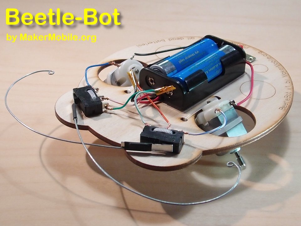
This build may take you two hours or more depending on how familiar you are with robot construction techniques. Whatever your level of skill and experience may be, we encourage you to slow down and follow this step-by step photoguide. That way, the chance of putting something on upside-down, or worse, of damaging a key part, will be minimized. This is real engineering, not Lego, and the parts donãt just snap together. You will have to look closely at your work and be your own quality assurance department! The more care and attention to detail that you can put into this build, the better the result will be.
We find itãs great if two people can work together on a build like this. Take it in turns to read each step aloud and study the pictures and the thing you are working on before taking action. Make sure you agree with each other about what is going to happen at each step!
Note: You can enlarge any photo by clicking on it.
Kit Contents
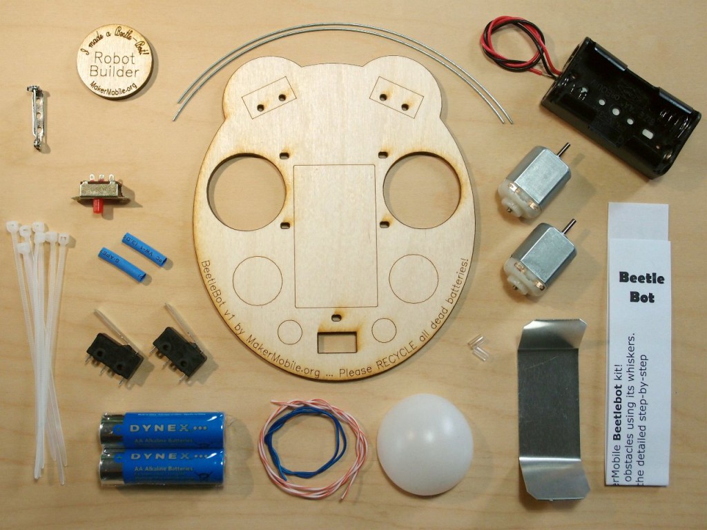
The Beetle-Bot kit contains:
1 Laser-cut main chassis
1 Aluminium motor mount
1 Battery holder with wires attached
1 Pair AA alkaline batteries (Recycle all your dead batteries at London Drugs, Staples or any recycling depot - please donãt put them in the trash).
2 Motors. We test them all individually when we pack the kits.
2 Microswitches
2 Whisker wires
1 Power switch
2 Pieces heat-shrink tubing (blue in this picture but colours may vary)
Approx 50cm plastic-covered copper wire. May consist of one or two separate pieces.
7 Zip-ties (only 6 are needed - one of these is a spare)
1/2 Ping-pong ball
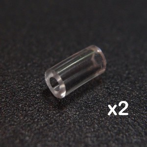
2 clear PVC ‘tiresã (or one piece of clear PVC tubing about 12mm / 0.5″ long that you will cut into two)
One laser-engraved button badge
One pinback for the badge
1 Slip of paper with a link to this page
Tools Required
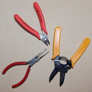
Hand Tools:
Needlenosed pliers, side cutters and wire strippers. Unless you are a pro, donãt try to get by without the wire strippers (and please donãt strip wires with your teeth!)
You will also need a metric ruler, but I forgot to put that in the photo Þ
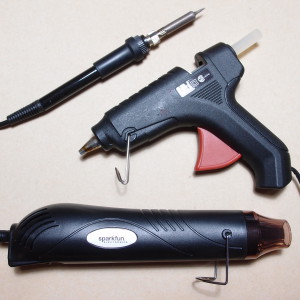
Power Tools:
A hot glue gun is essential. You can get them for under $4 at dollar stores. A small one is actually better than a big one for this project.
A soldering iron (and basic soldering experience) is desirable but not strictly essential. In this guide we show you how to make the connections by twisting wires. If you can solder the connections, your job will be a lot easier and the connections will be better.
The hot air gun is also desirable but not essential. This one is nice and small so you can put the heat where you want it.
Letãs Get Started
1. Prepare your wires
(a) First, find the right setting on your wire strippers. The right setting, or notch, is the one which cuts through the insulation but does not mark the copper wire inside. Take a minute to find this setting (practice stripping short lengths, say 5mm, of insulation off one of the rolled-up wires a few times). Look very closely at the wire to make sure that you have not cut into the copper, or worse, cut off some strands of copper. It seems like a small point, but itãs actually critical to get this right, or you will have problems later on.
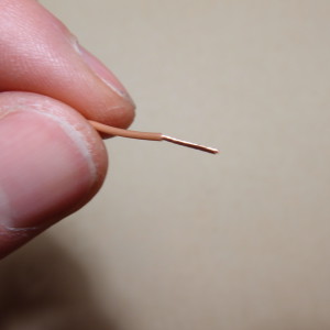 (b) From the rolled-up wires, cut 7 pieces each 50mm long. Strip about 10-12mm of insulation off each end. Twist the copper strands together by pinching the exposed wire strands tightly between your thumb and forefinger, and with your other hand, twisting the rest of the wire round about 10 times. The prepared wire ends should look like this:
(c) Cut the wires on the battery holder. You need to cut off 10cm of each wire and leave 5cm attached to the battery holder.
Leave the original ends of these two 10cm wires exactly as they are. The other ends of these two wires, and the wires still attached to the battery holder, should be stripped and twisted like the 7 short wires you just did. Again, be very careful not to damage the wires inside the plastic insulation.
2. Attach wires to the microswitches
The microswitches are the black boxes with metal levers attached to them. These will be attached to the botãs whiskers in a later step and will sense when it comes in contact with obstacles. These switches are sensitive (they have to be), and that also means that they could be damaged if handled roughly. Treat them gently and do not apply force to their levers when attaching wires to them or mounting them on the chassis. The black body of the switch can be held firmly but the levers canãt take much force, so be very attentive to how you hold them.
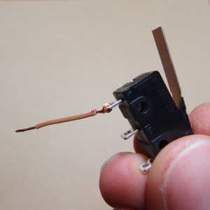
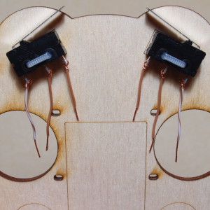
Take one of your 50mm wires and insert the end through a tab on the switch. Bend it back on itself and twist it around itself (copper around copper):
Repeat until you have 6 wires attached to the two switches.
IMPORTANT: If you are soldering your bot, be careful to limit the soldering time on each tab to about 2-3 seconds MAX or you could damage the switch and cause it to stop working.
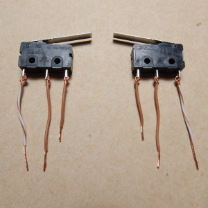
Here you can see the microswitches with their wires attached. Note that I took this photo before I figured out that the wires need to be 50mm long, so I actually had to replace the shorter ones Þ
If you are soldering your connections, you donãt have to twist the wires. Instead you can just hook them through the tabs and solder away.
3. Mount the microswitches to the chassis using zip ties
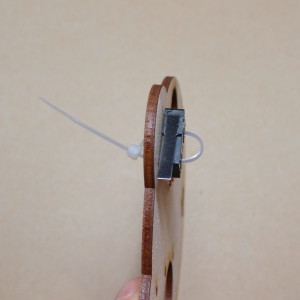
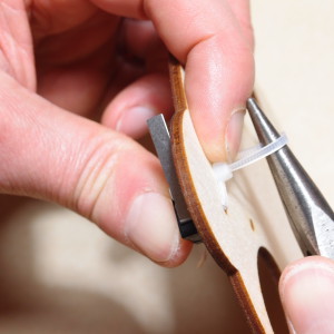
Position a zip tie as shown. Make sure you pull it nice and tight so the switch doesnãt move around BUT BE VERY CAREFUL NOT TO PUT FORCE ON THE SWITCH LEVER!!
You can use the pliers to get a better grip on the zip tie. Grab the end you want to pull and then twist the pliers around so the zip tie goes around the pliers as well as being grabbed in the jaws. Donãt try to hold the switch with the pliers.
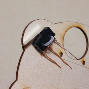
When the switches are snugly held against the chassis, use the side cutters to trim off the extra length. Trim right up against the ‘grabbingã end of the zip tie. It should now look like this:
4. Connect the battery holder
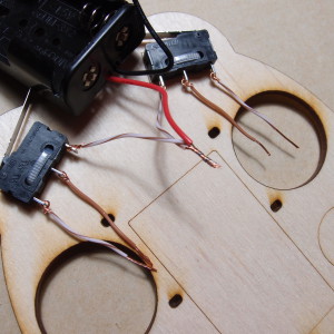
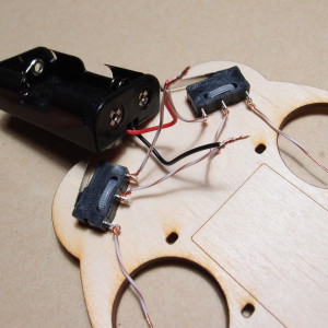
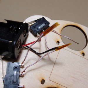
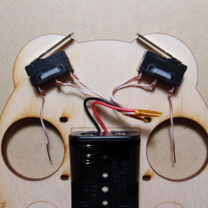
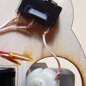
With the battery box out in front of the chassis (not over top of it), carefully line up the end of the red wire with the ends of the two inner switch wires. Twist them together tightly. Now twist the black wire tightly together with the middle switch wires (the outside wires on the two switches are still not connected to anything).
Now wrap the twisted-together connections with some kind of insulating tape (regular clear tape will do) to prevent them from shorting out your battery pack.
5. Mount the battery holder
Swing the battery holder around so it is over the rectangle in the middle of the chassis. Peel the backing off its self-adhesive tape and stick it down inside the rectangle. Put your thumb inside the battery holder and squeeze it hard for a few seconds against the chassis.
6. Mount the subframe to the chassis
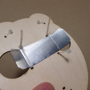
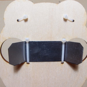
Using zip ties positioned as shown, fasten the aluminium subframe to the underside of the beetle-botãs chassis:
Make sure the zip ties are good and snug before you trim them (the subframe shouldnãt move around). Also check that itãs is in the centre of the chassis, neither off to one side nor the other.
7. Install tires on motor shafts
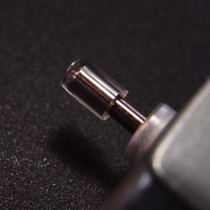
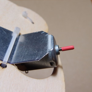
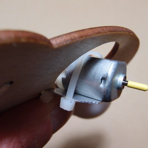
If your kit contains one piece of clear PVC tubing about 12mm or 0.5″ long, carefully divide it into two equal length pieces, using a sharp craft knife or scissors. Some kits may have the tires separately cut for you (older kits have a different style of tire which is already pre-installed on the motor shaft - you can see those in some of the pictures).
Push one tire onto each motor shaft. See how the tubing isnãt pushed on so far that the metal shaft goes right through it. Do it like this, so the bot wonãt be able to scratch tables, floors etc.
Note: When cutting the tubing, itãs difficult to cut straight across it at 90 degrees. If you notice that one side of a tire is sliced at a bit of an angle, put that end towards the motor and the ‘goodã end facing outwards.
8. Mount the motors on the subframe
Before you expose the sticky tape on the motors, do a trial fit with one of them to see where it will go. The body of the motor should protrude about 3-4mm beyond the edge of the subframe. OK, now go ahead and stick the motors down. You should still have three zip ties remaining, in which case you can use two of them to tie the motors to the wings of the subframe. If you used up your zip ties, you can use tape instead (it might be fine with just the sticky pad, but a little extra security in the motor attachment is a good thing).
9. Connect microswitches to motors
You can now go ahead and connect the remaining wire from each switch to the front terminal of each motor. Thread the copper wire through the hole in the motor terminal and twist the wire around itself:
10. Install power switch
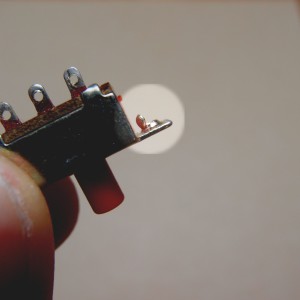
Look closely at your power switch. Like this one, yours may have some extra metal sticking up around the holes:
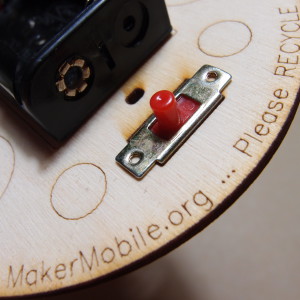
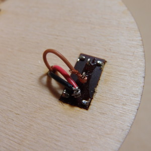
Use your pliers to pull off anything like this, then squeeze the side tab of the switch hard in the pliers, as close as you can get it to the pivot point, to flatten out any remaining unevenness. Drop the switch into its place below the battery holder. It should sit nice and flat against the chassis.
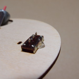
Apply a drop of hot glue as shown to hold the switch in place. Donãt put hot glue on the ends of the switch as it may run inside the switch and prevent it from sliding back and forth. How do I know this? Because I made that mistake myself, of course!
11. Connect motors to power switch
Now grab the two 10cm long red and black wires that you got from the battery pack leads. You should be able to fit both of the original (silver-coloured) ends through the hole in the right-hand-side switch contact. Bend them back around the metal tab and gently squeeze with the pliers to compress them against it. In this case, do not try to twist the wires around. Just thread them through, bend them back and squeeze them
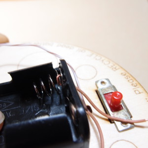
Thread the two wires through the small hole adjacent to the power switch and route them either side of the battery holder. Connect each wire to the remaining motor terminal (thread it through and twist it around, you know the drill…)
12. Connect the battery pack centre wire
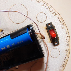
This one is a bit fiddly. Take your one remaining 50mm wire and make sure its bare end is well twisted together so the strands wonãt easily separate. Give the bare end a bit of a ‘Jã shape and put it through the hole in the end of the battery holder. Whatãs that? Yes, I know there are three holes. It doesnãt matter which hole you choose, so long as you are able to loop the wire under/around the metal battery contact wire. I put my wire through the middle of the spring and threaded it through the spring between the first and second turns, then hooked it around the spring as best I could…
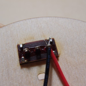
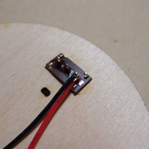
Insert one battery to hold this wire in place and thread the wire down through the hole. Connect it to the centre tab on the switch:
13. System Test
Put both batteries in the holder and slide the power switch. Both motors should run forwards. Pressing a microswitch lever should cause the motor on that side to run in reverse (itãs hard to see, but you can easily feel it if you are touching the motor shaft at the same time. Donãt grab the motor to stop it spinning - you could cause it to overheat and damage it). If a motor doesnãt run in one or both directions, check all the wiring on that side. In particular make sure that there are no strands of copper wire making contact with something that they shouldnãt be.
14. Install ping-pong ball
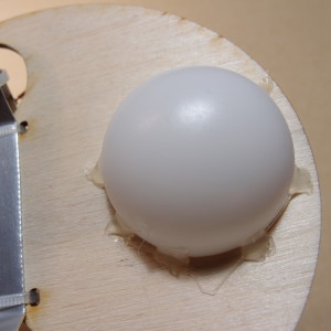
The ping-pong ball forms the third ‘wheelã that the Beetle-Bot stands on. Position the ping-pong ball under the chassis at the back of the beetlebot (it will cover up the switch and the wires going to it). Secure it in place with a few drops of hot glue.
15. Shape the whiskers
If you are not used to shaping wire, this is something that might take you a bit longer than you would expect.
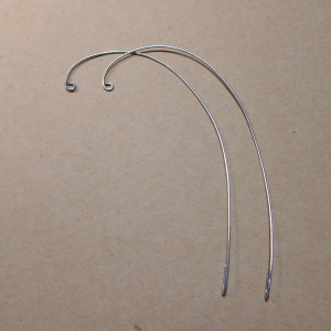
The reason for turning the very end of the whisker into a tight loop is to make sure there is no sharp edge that might hurt someone or get caught on something. You will need to use the pliers for shaping the wire ends.
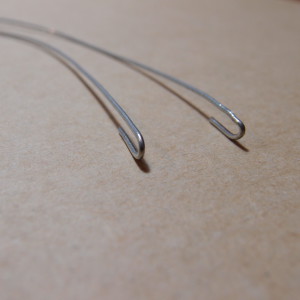
At the other end, you need to make a ‘Uã shape that is about 10-15mm long and between 3 and 4mm wide (it shouldnãt be wider than 4mm because it is going to be attached to the microswitch lever, which is 4mm wide).
When you have made a whisker that you like, try to make the second one identical to it in every way. Things to pay attention to include:
- Try to get out any kinks and bends that stop it from sitting flat on a surface.
- The U-shaped end should be perpendicular to the rest of the whisker, i.e. when you lay the whisker down on a flat surface, the U-shape should be standing up at 90 degrees to the surface. Try to get this as exact as you can by looking closely and critically at it and making small adjustments (use the pliers to hold the wire still while you give it a nudge or a twist with your other hand).
16. Install whiskers to microswitches
Slide a piece of heat-shrink tubing onto each microswitch lever. You will see that the front edge of the switch has a small step part-way along. Donãt slide the heatshrink as far as this step or it could get in the way of the switchãs movement.
Take one of the whiskers and slide the U-shaped end inside the heat shrink tubing on the front side of the switch lever (i.e. not between the lever and the switch body). Check that you did not accidentally move the heat shrink too far along the switch lever.
When you are happy with the positioning of the whisker on the switch lever, itãs time to apply some heat. If you have a hot air gun like my miniature one, switch it on and point it downwards onto the heat shrink. The nozzle should be about 30mm away from the heat shrink. After about 7-8 seconds remove the heat and allow everything to cool for a minute. Look closely - you should see the tubing is now stretched tight over the U-shape you made in the end of the whisker. If the tubing doesnãt seem to be pulled tight around the switch lever and the whisker end, give it a few more seconds of heat, perhaps from a different angle. Again, let the whole caboodle cool down. Too much heat can damage these switches.
If you have a large hairdryer-shaped heat gun, be very careful as they put out a lot more heat and you could easily melt something. It would be best to cover up the switch body with several layers of aluminium foil to insulate and protect it. Hold the heat gun farther away (perhaps 100-150mm) and apply heat in bursts of no more than 5 seconds (with cooldown time between) until you get the tubing to shrink tight around the whisker-to-switch joint.
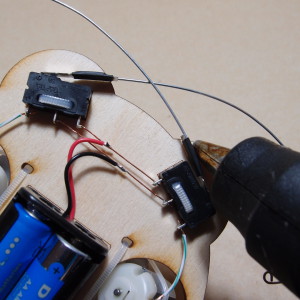
If you donãt have any kind of heat gun, donãt despair. A hairdryer is not hot enough, but a glue gun nozzle is. Grab a piece of paper towel and fold it to one-quarter size (so it is four times thicker). Use it to wipe any drips of glue from the hot nozzle of the glue gun (we donãt want to get any glue around the switch).
Touch the flat side of the nozzle against the heatshrink and move it gently back and forth (trying to get as much contact with the heatshrink as possible). Do this several times on the front side of the whisker, as well as on the back side of the lever (try not to touch the switch body though). After a few passes you should see the heatshrink tightening around the joint. Do a few more passes (for luck!) and call it a day.
17. Step back and gaze in awe at your robotic creation!
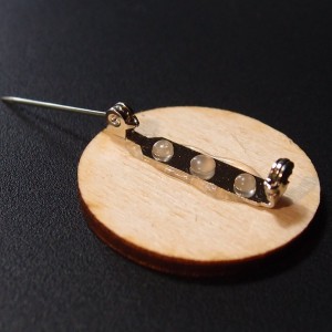
Congratulations - you built that! Like we said, itãs not Lego and some of those steps were pretty delicate. So well done. Before you unplug the glue gun, attach the pinback to the back of your Robot Builder badge:
Youãve earned the right to wear that badge, so wear it proudly!!
Fine Tuning your Bot
Check that the whiskers can move freely and that they activate the switches. If you need to adjust their shape at all, use pliers to grasp the whisker close to the switch end while you adjust with your other hand. This way you will avoid putting any stress on the switch or on the switch-to-whisker joint.
Put the bot through its paces. Its tiny wheels need a hard floor rather than carpet, and its favourite thing is to bump into hard objects like books and wood blocks, rather than curtains and such. Set up an obstacle course, or a maze - have a race with another beetlebot. Whose bot is faster? Whose makes better navigational decisions? Does the shape of the whiskers affect performance?
A note about batteries:
The right side battery powers the motors forward, while the left battery powers reverse gear. Since the Beetle-Bot only reverses a motor when it encounters an obstacle, itãs quite possible that the forward battery will run out before the reverse one. In fact, when the forward motion starts to slow down it might be a good idea to switch the batteries over!
When you do have to replace a battery (or batteries), please donãt throw the old ones in the trash. When the trash is buried, the battery sits in the ground and causes pollution. You can drop off old batteries to be safely recycled at many stores such as London Drugs, Staples or many other places that sell batteries.
Enjoy Your Robot !
Questions or suggestions? Email us or leave a comment below - weãd love to hear from you!


