Your kit contains the following parts:
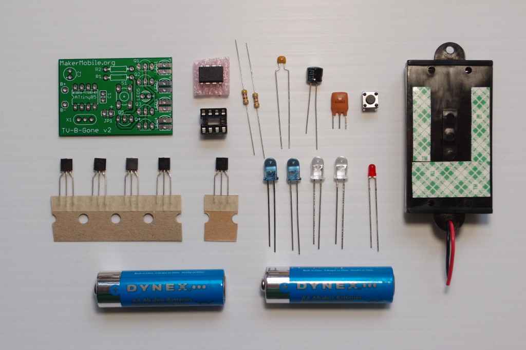
From left to right we have:
TOP: Circuit board (PCB) with names and positions of all components marked in white, microcontroller chip (an IC - Integrated Circuit) and its socket, resistors R1 and R2, capacitors C1 and C2, ceramic resonator X1 (not in the RISC edition), pushbutton switch S1, battery holder with adhesive foam tape (tape may or may not be pre-applied to battery holder). Please keep the chip in its antistatic foam until the last step of this build process as it is easily damaged by static, especially if you live somewhere dry)
BOTTOM: Transistors Q1-Q4 (all identical), transistor Q5 (different from the other four), infrared emitters LED1-LED4, indicator LED5, two AA batteries.
TIP: Don’t take the transistors out of their paper tape until you are ready to solder them in place. If you mix up the five transistors you will have to peer at their microscopic part numbers to find out their identities. Q1, 2, 3 and 4 are PN2222 while Q5 (the odd one out) is PN2907.
Getting Ready
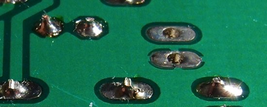
If you haven’t soldered before, or you are a little rusty, it is not a good idea to try to hone your skills as you build this kit. Many components can be damaged by excessive heat caused by taking too long to solder a joint, so watch a youtube video or three and practice plenty on pieces of scrap board and surplus components until you can quickly produce solder joints that look close to this:
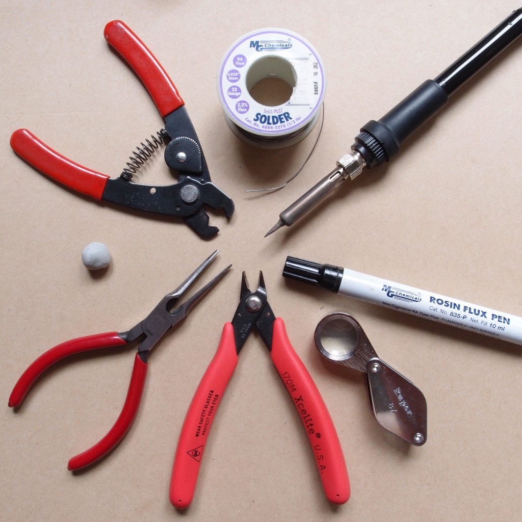
Now gather your tools. You’ll need …
- a soldering iron with a reasonably fine tip
- electrical solder (ideally no wider than 0.6mm)
- needlenose pliers
- side cutters
- wire strippers
- a well-lit workspace with a mat or similar to prevent burns to the work surface.
You may also find the following items helpful…
- a magnifier to check your work
- a blob of blu-tack (a.k.a. poster putty) for holding components in place against the board while soldering
- liquid flux to make soldering much easier.
When soldering the resonator (step 8), I recommend you apply a small amount of flux to both sides of the PCB as well as to the legs of the resonator. This will cause solder to stick to and strengthen the very thin legs of this component.
Don’t forget to have a damp sponge in your soldering stand to wipe (not poke) the iron tip clean as you go along. If you find that solder beads on the tip, the soldering iron has likely been running too hot and the tip has oxidized, showing a grey or black colour. Tips can sometimes be saved - unplug the iron and let it cool completely. Then gently clean the tip with fine steel wool till it looks less black and more metallic. This may take 10 minutes or more. Before you switch it back on, dial the heat down to no more than 700F/375C. If you have one of the red Weller soldering stations, set it to 3. The moment the tip is hot enough to melt solder, coat it with solder, then wipe it off and recoat. Do this several times. The tip should now be capable of holding molten solder. It’s virtually impossible to make a nice solder joint with a tip that’s in bad condition and can’t hold solder, so it really is important to get this sorted out first.
OK… Let’s start by looking at the PCB. This photo shows the component side. All the parts are going to sit on this side and you will do all your soldering on the BACK.
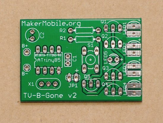
Notice how every part is identified by name AND its position and correct orientation is shown as well. All the LEDs as well as capacitor C2 (the big one) have a + sign next to one of the holes. That’s because these components are polarized - it matters which way round you insert them. For all these parts, make sure you insert the long lead into the hole marked +. Notice also that the transistors all have a flat side and that this is shown on the circuit board. Make sure all the transistors get inserted as shown on the PCB. Finally, look at the spot where the IC socket goes. The white printing shows a notch on the left side, and the socket has a moulded notch at one end, so when you solder the socket to the board, align the notches. The other parts (R1, R2, C1, X1 and pushbutton S1) can be inserted either way around.
The Build
Step 1 Pre-bend the leads of resistors R1 and R2 (these two parts are identical) and insert them into their places on the PCB: 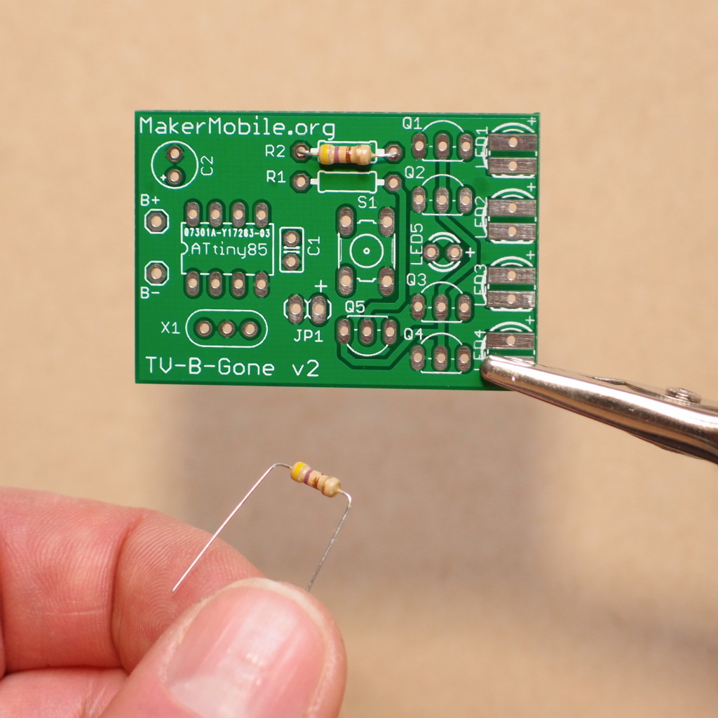
Hold the resistors in place with blu-tack (poster putty), or by bending their leads outwards on the back side of the board… 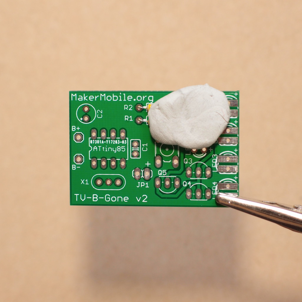
Flip the board over and solder the resistors, then clip off their leads.
After clipping, the solder joint should protrude no more than 1mm above the surface of the board. Scroll down to the end of this tutorial to see how your solder joints should look,,,
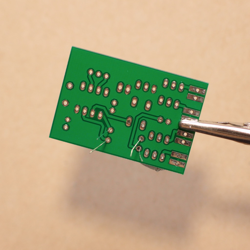
Step 2 Solder the IC socket in place. Line up the notch with the notch in the white printed outline. 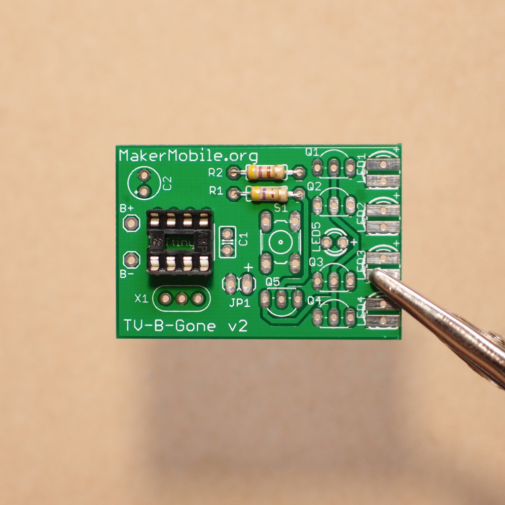
Step 3 Solder the pushbutton switch S1:
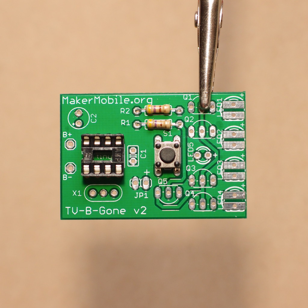
Step 4 Solder capacitor C1 in place. Note: if the lead spacing is too wide for the holes, use needlenose pliers to very carefully and gently adjust them. Don’t put any force on the leads where they join to the capacitor!
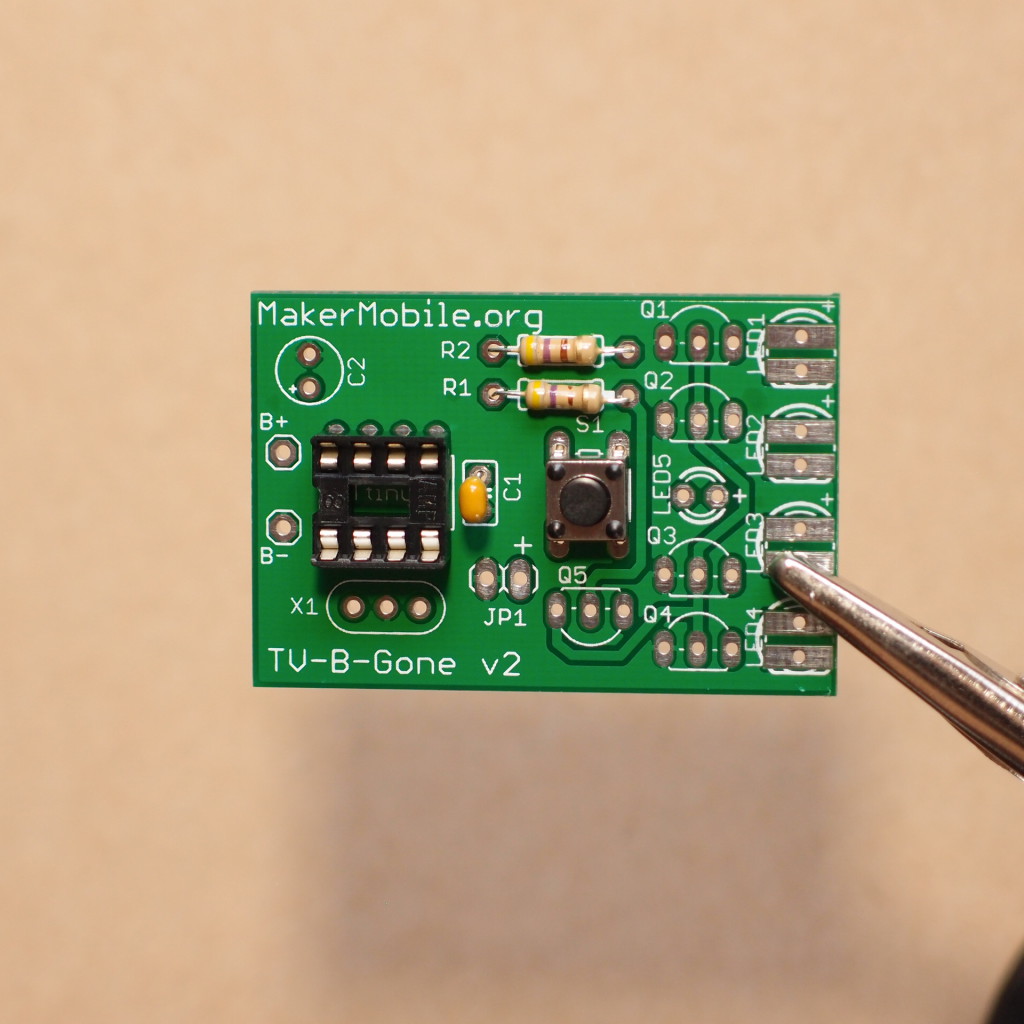
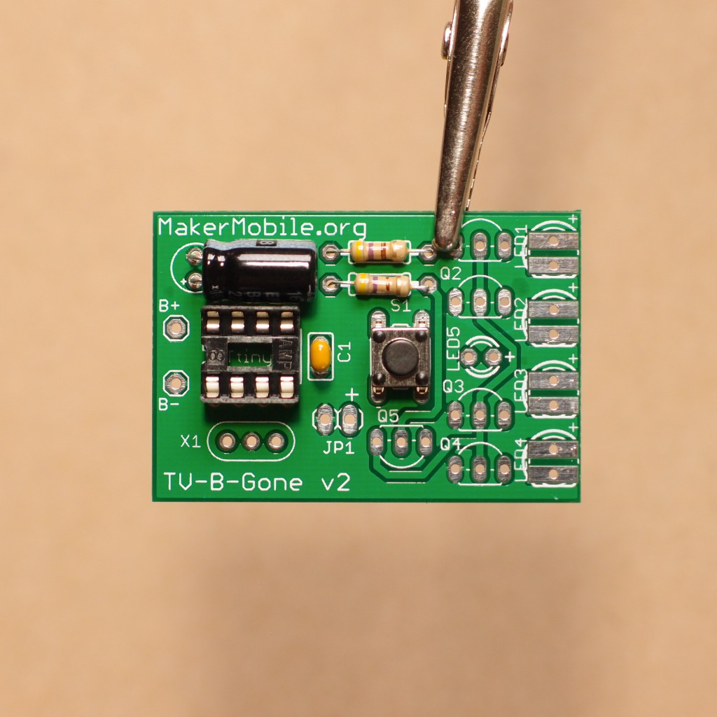
Step 5 Solder capacitor C2 in place, making sure to observe the correct polarity (long lead goes in the hole marked +). If C2 is a short type (a cylinder about 5mm long), you can just drop it straight into its holes. If it is a longer can type, it will need to be installed ‘lying down’. In this case you will want to carefully pre-bend the leads before inserting C2 into the board. If you don’t, and you subsequently try to lay it flat, it will be impossible to do so without damaging it and/or the PCB. Here’s what the pre-bend would look like for this longer-can type of capacitor:
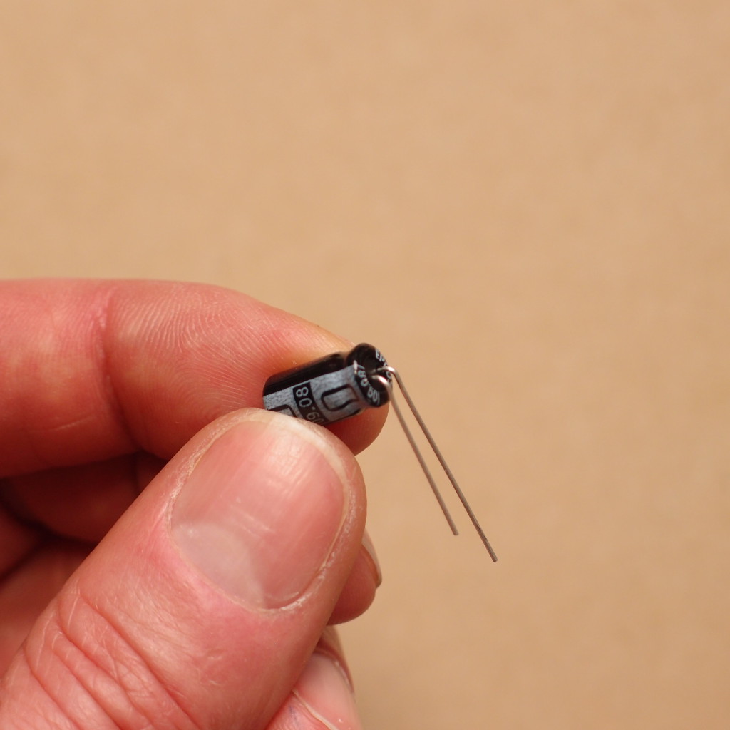
And here’s the board after soldering C2 in place (short and long types both pictured for comparison: 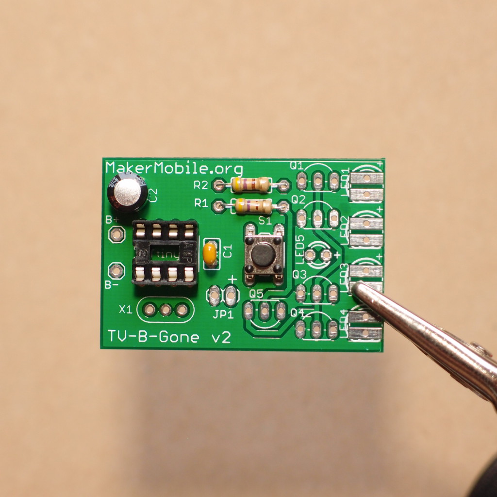
Step 6 Solder transistors Q1 - Q4. Make sure to align the flat side of each transistor with its outline on the board. To avoid overheating these parts, solder all four on their right side, then do all four centre leads, then finally all four left hand side leads. Clip off each lead as you go along, 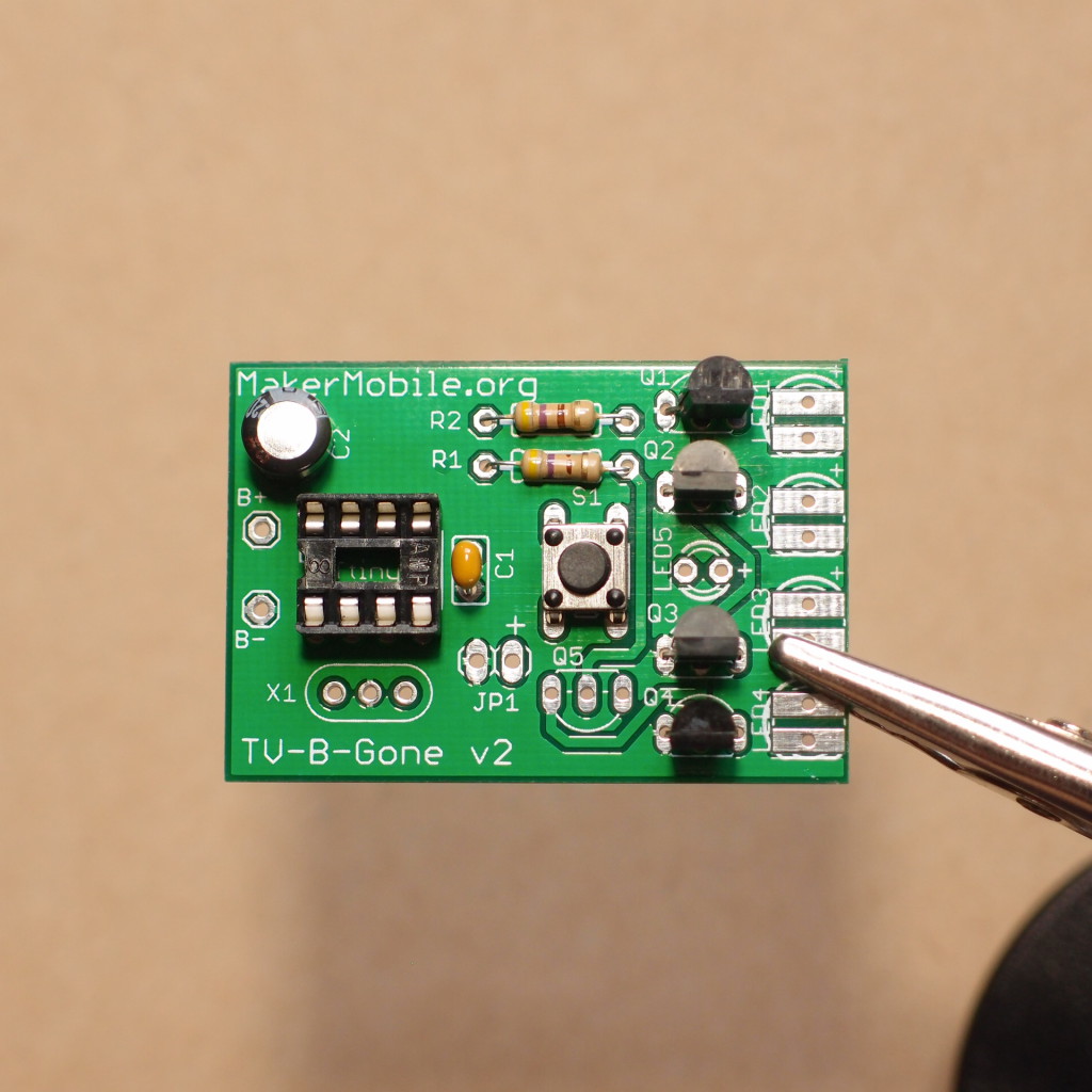
Step 7 Solder transistor Q5. Notice that this one is ‘upside down’ compared to the other four transistors: 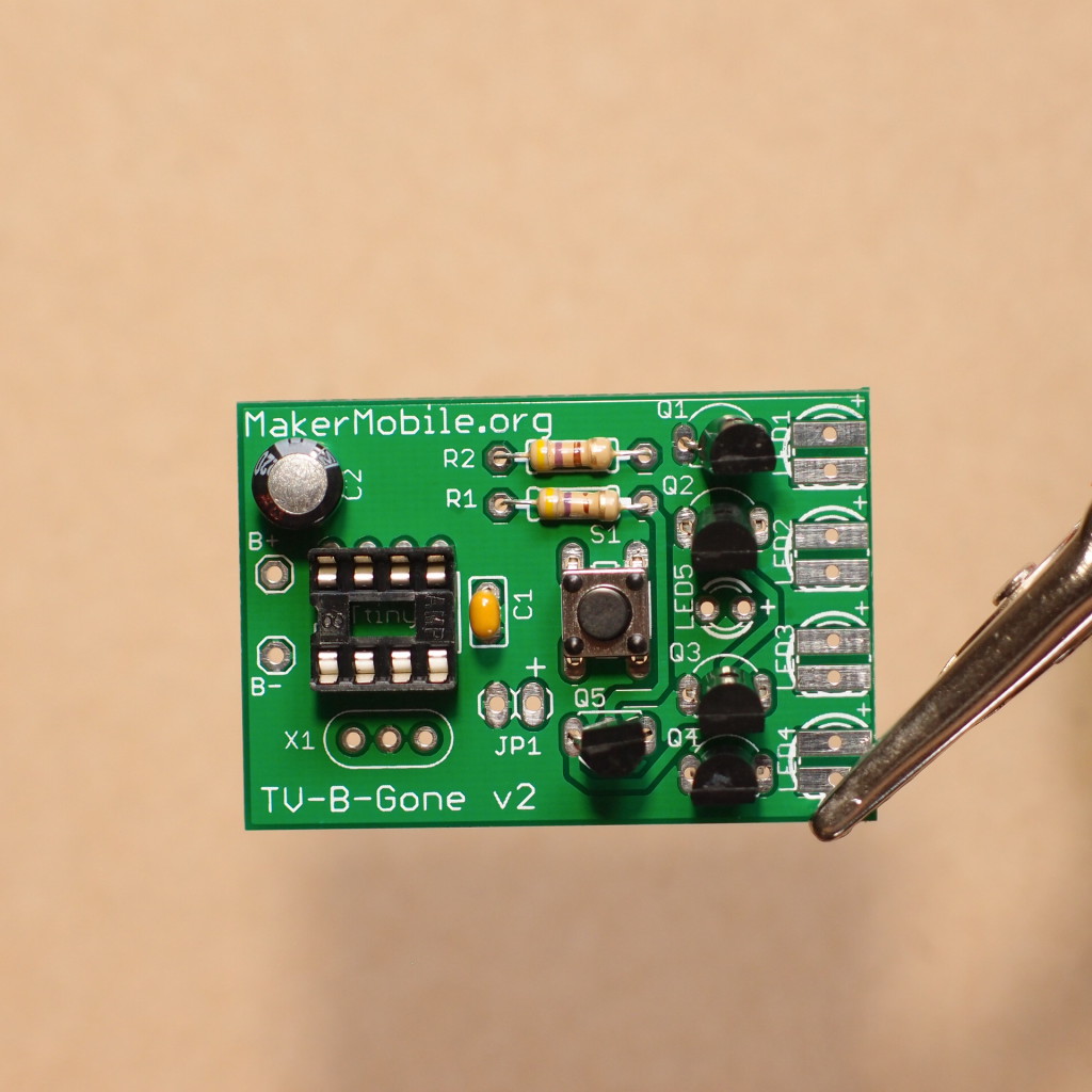
Step 8 [skip this step if you have a TV-b-Gone RISC edition]
Solder resonator X1. Tip: lean the resonator against the IC socket and solder it like that. It will be less vulnerable to damage in that position. 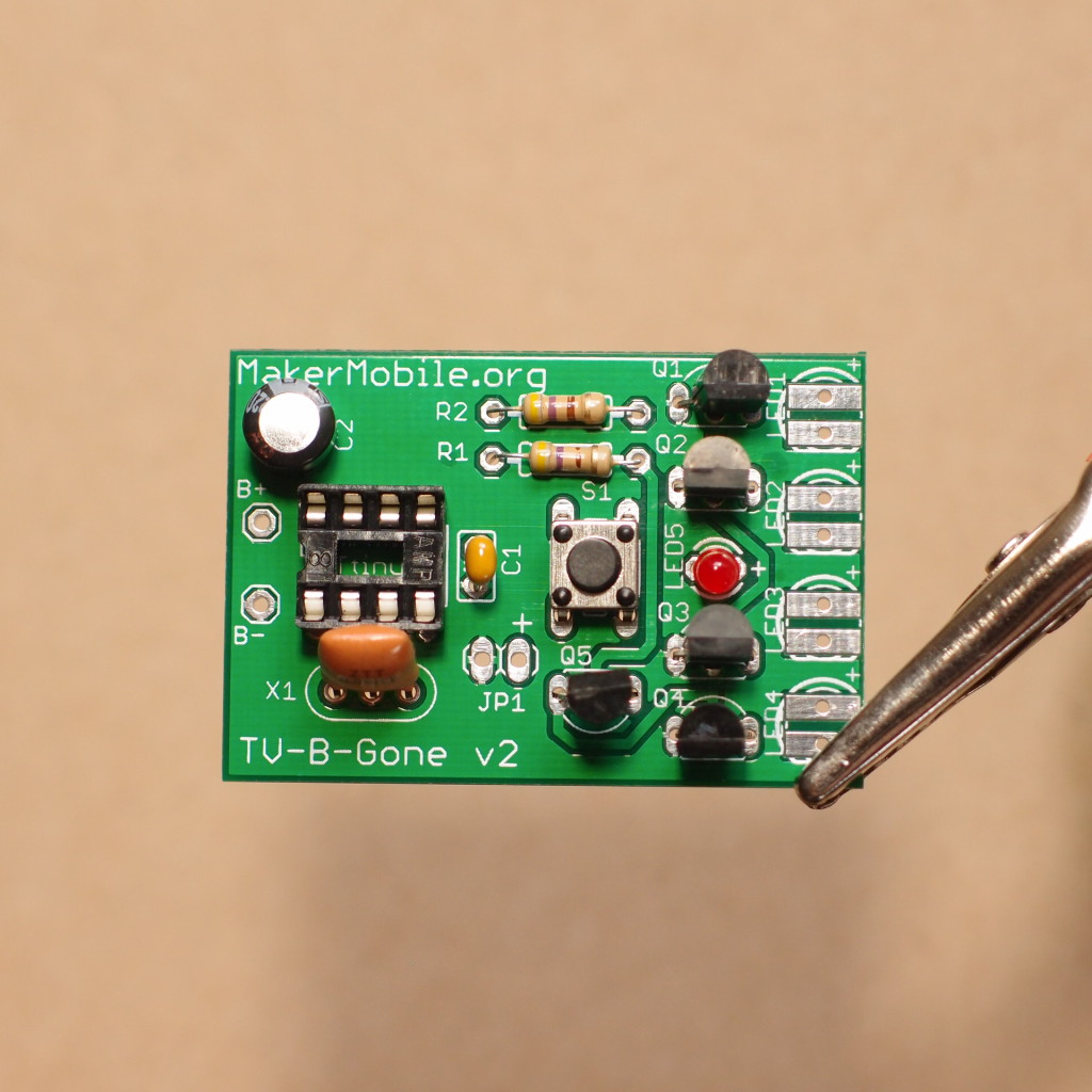
Step 9 You might have noticed that the last shot also shows the red LED soldered in place! Make sure the long lead goes into the hole marked +.
Step 10 Holding the leads of the infrared LEDs with needlenose pliers as shown here, bend them downwards through 90 degrees. Notice that the long lead is at the top left in this picture, and that the pliers are touching the body of the LED on the right hand side (if you allow the pliers to touch the LED across its entire width, you will bend the two leads at different distances from the LED - try to aim for equal lengths from bend to LED). 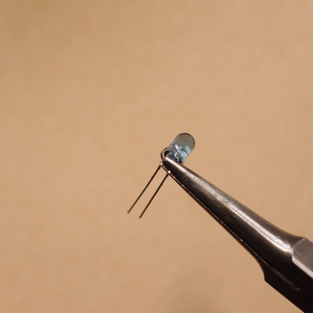
Insert the infrared LEDs with their long leads in the holes marked + and solder. Many kits have two narrow-angle LEDs (which are sometimes but not always coloured blue-grey) and two wide-angle LEDs. It doesn’t matter which one goes in which of the four spaces. Here we have put the ‘high beams’ in the centre, like on a car: 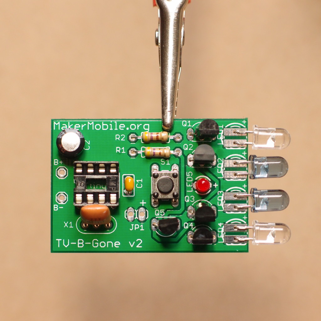
Step 11 We’re almost done. Look at the battery holder. If the red and black wires are not already threaded through the hole on the end lug, do that now, taking care not to kink them or pull them too hard. Now trim the wires so that they are no longer than they need to be, then strip about 3mm of insulation and tin the ends (apply a little solder to the exposed wire to make the strands stick together). Put the tinned wires into the PCB (red to B+, black to B-) and solder them. Clip off any excess.
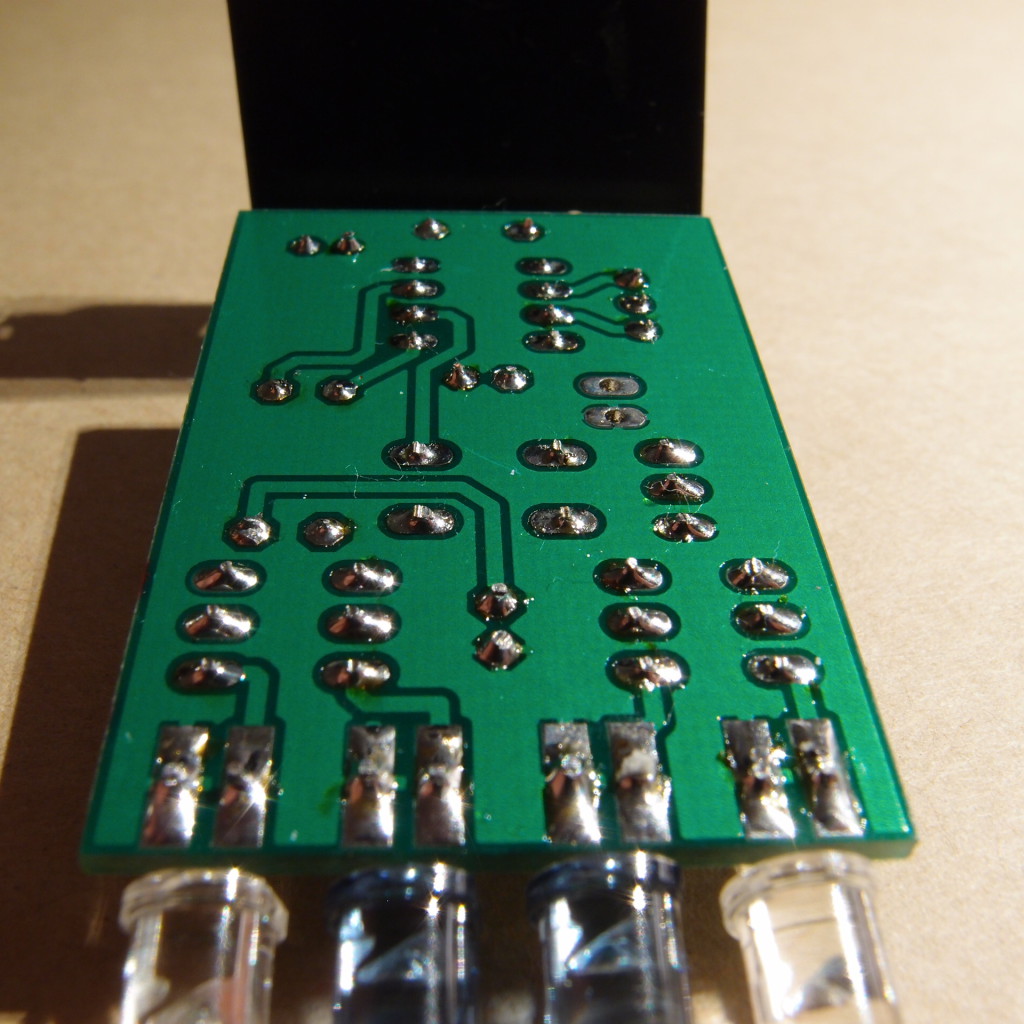
Step 12 Inspection. Take a few minutes to look closely at your work. Look for bad joints, blobs of solder and solder bridges between pads. Clean things up without applying excessive heat to anything. Finally check that all leads and wires are clipped close to the board, and that there are no wire clippings floating around that could cause short circuits. Get a second pair of eyes on it if possible. This shot shows what the back of the board should look like. Note the quantity of solder used and the shape of the joints. All leads, including the IC socket and the pushbutton, have been clipped within 1mm of the board.
Step 13 Remove the microcontroller from its protective antistatic foam and carefully, gently, insert it in its socket. There is a round dot marked on the top surface of the microcontroller and the end with the dot must go at the end of the socket that has a notch in it (the left hand side in our photos). If you soldered the socket onto the board the wrong way around, it doesn’t really matter - what does matter is that the end of the chip with a dot should be positioned towards the battery connections marked B+ and B- (i.e. towards the LEFT hand side of the PCB as shown in our photos). You might need to gently bend the pins of the microcontroller to get it to fit into its socket. The best way to do this is to hold the chip against a flat surface and push gently, bending all four pins on one side at the same time. When the chip is in its socket, squeeze it til there’s no gap, or no thicker than a piece of paper, between the two.
Now insert the batteries. LED5 should flash for two seconds if all is well (if it doesn’t, remove the batteries and check your work until you find the fault). The next check you can do is to aim the infrared LEDs at a digital camera, webcam etc and hold the button down for a few seconds. You should see some purple flickering as most digital cameras are sensitive (some more than others) to infrared light. OK, it works, now position the adhesive tape and stick the circuit board to the battery holder. Congratulations, you’re the proud owner (and maker) of a MakerMobile enhanced TV-b-Gone - a member of a very exclusive club!
Version 2 incorporates many improvements over the version 1 kit that is still sold elsewhere on the Internet. The most obvious difference (apart from the cleaner, simpler and better labelled PCB design) is that it only transmits as long as you hold the button down. That, plus the fact that we’ve optimized the order in which the codes are transmitted, makes for much longer battery life than v1.
To find out more about the modes and features of TV-b-Gone v2, have a look at the TV-b-Gone v2 User’s Guide.
To find out about the TV-b-Gone RISC edition, have a look here.


Thanks for this. I picked up my tvbg today at the Vancouver Mini Maker Faire and put it together. Works great! Time to head to a big box store and cause some chaos…..( naah …. those poor clerks don’tget paid enough….I’ll find somewhere more fitting)
Cool! How did you find the tutorial? Any suggestions on how it could be better or clearer?